Putting contact force on the gel z axis
A Stage-1 tactile action → flow encoder, and an honest account of what the change did and did not buy. 3 variants × 3 seeds.
Summary
What changed
Stage 1 maps a 9D sensor action to tactile optical flow. The action reaches the encoder as a
rasterised displacement map on the 16×16 latent grid. That map used to be laid on the
rigid (OptiTrack) frame's z=0 plane through the rigid origin — but the real
gel normal is roughly −y and the gel surface sits 66–72 mm away, so
dz was never press depth and the rotation lever arm was taken about the wrong point.
The fix composes the world poses with the gel calibration before the existing converter, so
+z is the true gel axis. Contact force — from the "purple point"
(force_*_target_pose, the observed pose advanced along the press direction by the
penetration depth) — is then a pure z quantity, appended as log1p(N)
plus a contact flag. Three variants are compared: rigid frame (control, retrained on
the same episodes), gel frame, and gel frame + force.
1. Is the predicted flow even right?
Before trusting any comparison: warping frame t by the ground-truth flow has to land on frame t+1 better than doing nothing. If it does not, the sign, axis order or scale is wrong and every number here is meaningless. Swept on the highest-motion held-out adjacent frame pairs (0.167 s step, no chunk-summing involved).
| warp convention | PSNR vs real t+1 | vs static |
|---|
Direction is good, magnitude is short
| variant | EPE | direction cos | |pred| | |GT| | magnitude ratio |
|---|
Held-out, one transition, active cells only. The predictions point the right way but systematically under-shoot — the regression-to-the-mean of an L1/L2 flow loss, which plain EPE hides.

2. Why warping frame t does not give you frame t+1
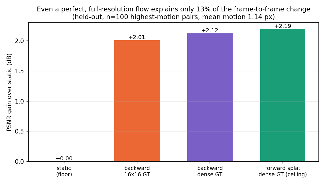
"Next frame = previous frame warped by the flow" is only true when the change between frames is advection. Here it mostly is not. An oracle ladder on the same held-out pairs, replacing the model with progressively better flow until the flow is perfect and full-resolution:
First, the scale of the thing
Two adjacent tactile frames are already about 99% identical — they differ by roughly 1% of the intensity range. That is why simply copying frame t already scores 36 dB and a perfect flow only reaches 38 dB. PSNR here is almost entirely earned by the frames being similar to begin with, so it is a misleading yardstick. The question is not whether the warped frame looks like the next one — it does — but how much of the change the flow accounts for.

Success and failure cases
The same operation, on the pairs where it works best and worst. All six are above-median in both frame change and motion, so the failures are not quiet frames with nothing to remove.

| mean |GT flow| (px) | n | fraction of the change removed |
|---|
It is not the tracker's fault
The obvious objection: AllTracker saw both frames, so surely its displacement is the one that maps one onto the other. That conflates two different objects — correspondence (where a material point went) and reconstruction (a field that maps It onto It+1). They coincide only under brightness constancy. Compare against a method whose entire objective is reconstruction:
| method | PSNR vs real t+1 | vs static |
|---|
What the residual is made of
Every candidate mechanism co-varies with how much motion there was, so raw correlations cannot separate "flow-invisible" from "simply more motion". These are partial correlations with in-plane motion held fixed, and the bars are binned inside a single narrow motion band.

| mechanism | raw corr | corr with motion | partial corr motion held fixed |
residual across bins at fixed motion |
|---|
3. Does the gel frame + force help? Where the difference lives
Same held-out windows for every variant, split by what the video does inside them. Contact state comes from the per-frame contact area at the transition's start and end frame.
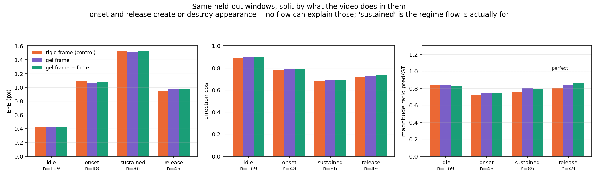
| contact event | n | |dI| | |GT| flow | magnitude ratio rigid / gel / gel+force |
direction cos rigid / gel / gel+force |
|---|
Aggregate numbers, and why they read flat
These average over every held-out window, including the ~48% with no contact at either end where all three variants are identical. Read them with the split above in mind.
4. Fixing the magnitude deficit — and why it only half works
The loss had a cosine term supervising direction independently, but nothing supervising
length independently — so under-shooting was the cheap way to cut it. Adding
mag_weight · | |pred| − |target| | on active pixels (default 0, so existing
runs are untouched; the w=0 control reproduces the baseline to the digit):
| mag_weight | EPE | direction cos | magnitude ratio |
|---|


5. Generalization: seen vs held-out
6. Long horizon: integrating the flow
Per-transition EPE says nothing about what the flow does once you accumulate it, which is how Stage 2 consumes it. 20 consecutive latent transitions (0.83 s each, ~16.7 s), teacher-forced on ground-truth latents so this isolates flow integration rather than world-model rollout.

| drift from GT trajectory (held-out) | +4.2s | +8.3s | +16.7s |
|---|
The frame carried forward by flow alone
7. Dropping the VAE: Stage 1 in raw pixel space
Stage 1's target was always pixel flow — the only VAE component was the state input
z_t, and its grid (16×16) came from the VAE rather than from anything about the
task. So: replace the latent with the tactile frame itself through a stride-4 conv stem, move to
24×32 (AllTracker matches at stride 8, so that is its real output resolution;
pooling the dense field there costs 4.0% against 7.1% at 16×16), and use native px, dropping
the 256×256 square-resize that only ever existed for the VAE.
| variant | grid | temporal unit | direction cos | magnitude ratio |
|---|

Input ablation, pixel stage
| inputs | active EPE | cos |
|---|
Both inputs contribute and together beat either alone, so the encoder is genuinely using the action rather than just reading the frame.
8. The video branch in pixel space — where warping finally works
The same treatment applied to the VIEW encoder: state = the camera frame instead of the 48-channel Wan2.2 latent, grid = 24×32 (AllTracker's stride-8 output), units = native px over the full frame. The old view raster additionally threw away everything outside a central 192×192 crop — an artifact of the VAE wanting square input — so the 12-channel ActionImage was rebuilt in full-frame coordinates.
| inputs | active EPE | direction cos | magnitude ratio |
|---|
Do the predicted flows move pixels to the right place?
This is the question the tactile branch answered with a flat no — a gel image is shaded depth, so even a perfect flow explained only ~12% of the frame change. A camera view is genuinely advective, and it shows:
| carry frame t forward by… | PSNR vs the real frame 0.83 s later | vs static |
|---|

Everything trained here
| run | epochs | active EPE | cos |
|---|